 Andrew Betts


Paper lanterns are a really cool vibe. But lighting them up daily means they need to be wired into mains power. This is often done around temples or restaurants with a single bulb hanging inside the lantern as part of a festoon lighting string. I wanted a slightly cleaner look with no visible bulb. I also wanted a super thin hanging wire which didn’t look like an electrical cable, and I wanted the lanterns to animate - ie. glow by fading their brightness on and off like candlelight.
Here’s what I came up with:
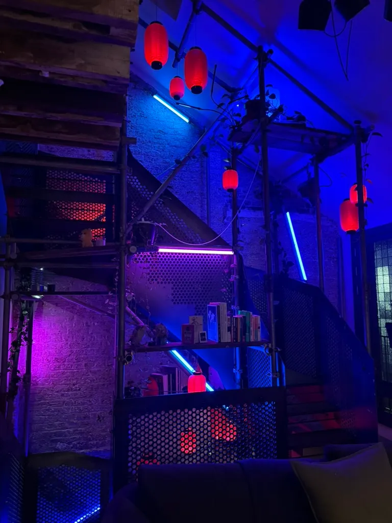
I love doing projects with WLED - in the image above you can see some ‘neon’ tubes that I made in an earlier project, and I know WLED can do a decent simulation of candlelight using RGB LEDs. For this project I decided early on to use WLED with WS2812B LED strips, and focus on finessing the aesthetic of the lighting and wiring.
Fitting the LEDs
I have two types of lantern - the small type has a solid base with a battery compartment for 2 x AAA batteries and a single white LED to light up the lantern, and the larger type is just paper with holes at the top and bottom. Both types work by stretching a stiff wire between the top and bottom rings, to hold the lantern open.
Since one of the lanterns already has lighting, I did consider replacing the 2xAAA batteries with a full-time 3V power supply, but to acheive the glow effect I’d need to add a PWM mirocontroller, and 3V is a really hard voltage to get to travel any distance, so we’d probably also need voltage converters in every lantern as well.
Better just to add my own LEDs. A ring of LEDs facing inwards around the base of the lantern minimises the visibility of the LEDs themselves, avoids the need for joining strips together, and provides a nice even light across the inner surface of the lantern.
A consistent number of LEDs per lantern makes things easier with WLED, because WLED has a concept of ‘grouping’ pixels, so you can treat every n LEDs as one LED. If I used a different number of LEDs per lantern I’d have to instead use WLED’s “segments” feature to create a segment for each lantern. This felt a lot more fiddly (I already use segments for the neon tubes and I find it kinda annoying, especially the way it creates tonnes of entities in Home Assistant). I figured I’d use a strip of 6 LEDs for each lantern.
Now we need something to stick the LED strip to. Because the smaller lantern already had a base with an LED on it, and the way the stiffening wires connect to the bases was also different, I designed a slightly different mount for each lantern type, and 3D printed 20 of them:
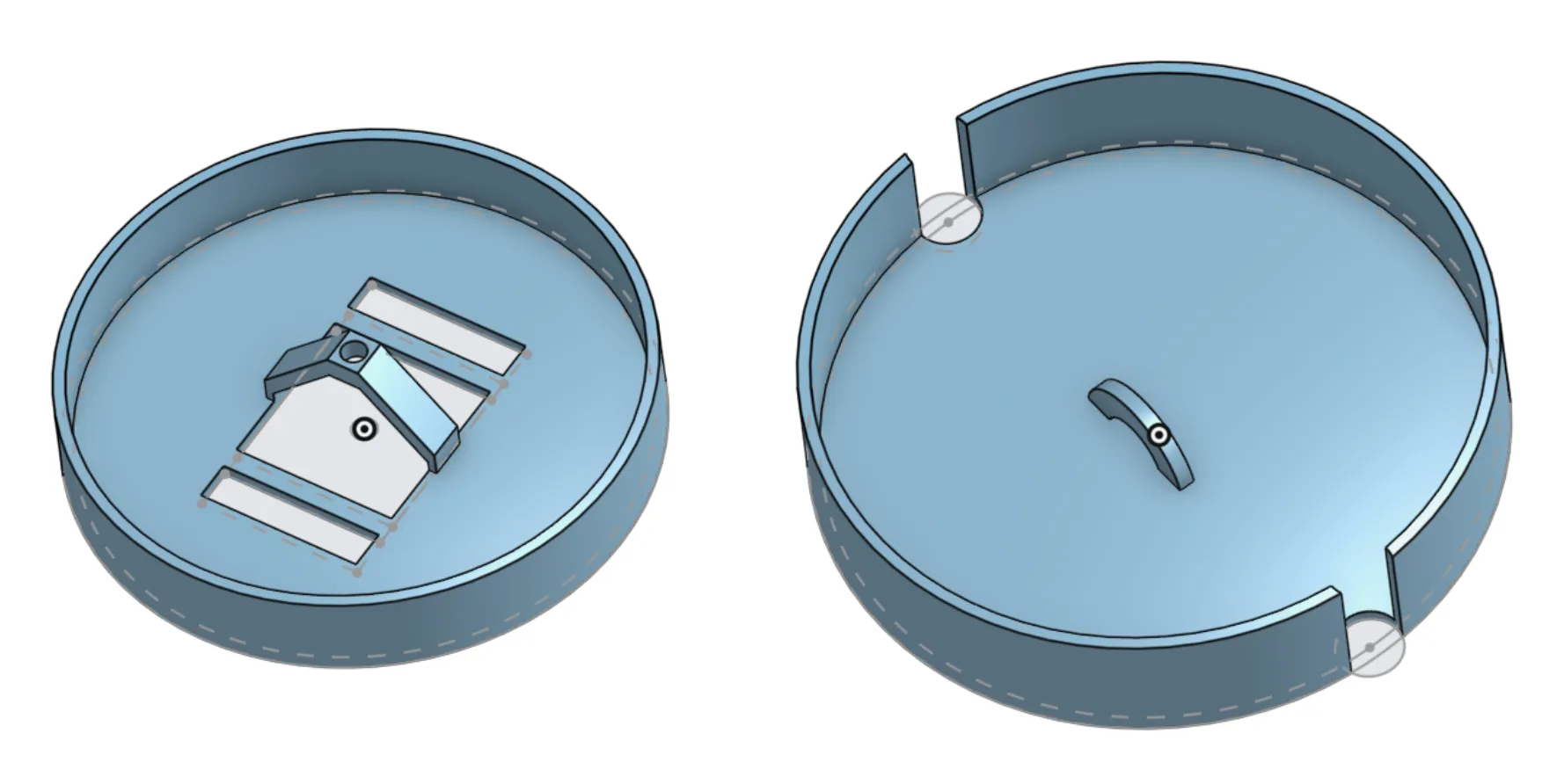
Wires could then be soldered to the strip - three on one end (5V, data in and ground) and one on the other end (data out). The bundle of wires is then zip-tied to the 3D printed mount, and threaded up through the top of the lantern.
Wires for lanterns
This project needs four conductors down into each lantern, and at least three running between lanterns. Something like this:
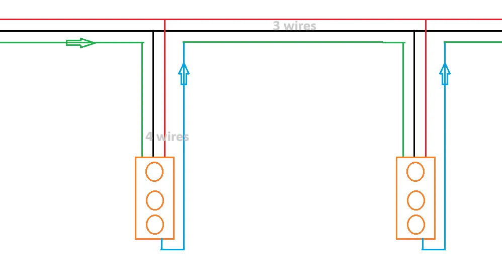
And I really wanted the wires to be thin. It can’t look like there’s a fat electrical cable going to each one.
USB cables have at least 4 conductors (typically 6, actually), but it seems hard to find USB cables with an outer diameter of less than 4mm. Interestingly ethernet cables seem to be far more available in narrower gauges despite having more conductors - Unifi’s ultra-thin patch cables are also surprisingly affordable, and another advantage of ethernet cables is that they contain twisted pairs, making it easier to reduce noise on data lines. But their conductors are very thin, leaving me worried about voltage drop. USB cables typically have two thicker conductors for power, and 4 thinner ones for data, which suits my use case quite well.
I strung up a couple of lanterns with a 4mm USB cable, a 3mm Unifi patch cable, and a 1mm waxed jewellery cord. And I dunno why I’m obsesed over this but these thick cables just aren’t gonna do it for me.
Next up, I tried moving to individual conductors. Someone on a forum thread suggested enamelled copper wire so I bought some of that. This stuff is really beautiful - copper conductors coated in a very thin layer of transparent enamel. But it’s also fragile, kinks easily, and proved be be really hard to solder onto reliably.
Finally I disovered wire-wrapping wire, almost as thin as enamelled wire but with a conventional plastic sheath - the reel I bought had a conductor diameter of 0.2mm and outer wire diameter of 0.6mm. A bundle of four of these wires looks cool, gives me cyberpunky vibes like messy overhead power infrastructure.

Super easy to strip and solder, nice and flexible. We have a winner.
USB junctions
That gets us four conductors down into each lantern, but now we need to connect the lanterns together in a string. The 0.2mm conductors are way too thin to carry power for multiple lanterns, so we need a power bus that each lantern can plug into. I also wanted to be able to easily move the lanterns around to experiment with hanging length and lantern size in different places.
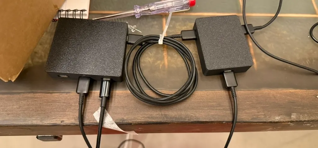
So, let’s put USB-C plugs on the end of each lantern’s hanging wires, and make junction boxes with USB sockets.
To make this as reliable as possible, I used prefabricated USB cables, cut them and soldered the conductors to the wire-wrapping wire, then 3D printed some junction boxes that I could fit USB sockets into.

This enables all the 5V power connections to be tied together (and all the grounds), providing power injection at every lantern, and wiring the data-out from each lantern to the data-in of the next one.
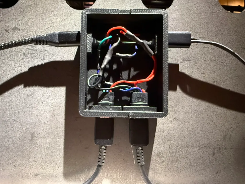
The USB sockets I used came with four wires, which was ideal for me.
Controller and WLED setup
I used to make WLED controllers from ESP32 boards myself, but it’s now easy to buy dedicated WLED controller hardware with WLED preloaded, basically an ESP32 with a built in level shifter in a nice case with lever terminals for inputs and outputs, and power passthrough. Some come with microphone too in case you want to run WLED’s sound reactive build. For the sake of an extra five quid, I see no reason to do all that myself, so I picked up a few of the prefabricated controllers from AliExpress.
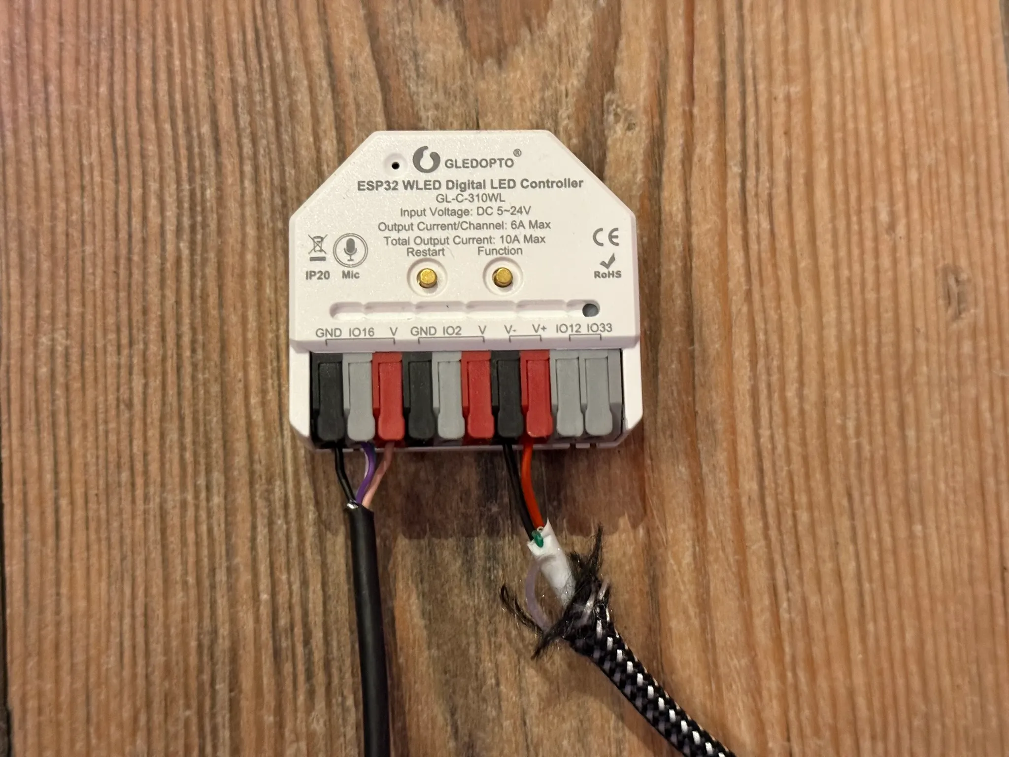
I chopped a USB-A “charge-only” cable (which contains only 2 conductors) in half, connected the positive and negative wires to the power input and ground on the controller, and plugged the USB plug into a USB power supply. The controller booted up and exposed a WLED-AP wifi network, which can be connected to from a phone or laptop to configure the wifi settings on the controller.
Having got the controller on my Wifi, I found its IP address used my router’s web interface, and connected to that IP in a browser.
Now I connected my LEDs to the VCC, GND and DATA terminals of the controller. The controller I bought actually provides two data outputs, so if yours does too, take note of which GPIO is labelled on the one you use.
The main things I configured in WLED were:
- In settings > LED preferences
- Output 1 (matching the GPIO of the output I wired my LEDs into) LED count: number of lanterns x 6 LEDs per lantern
- Output 2 LED count: 6 (Just to keep the second output configured)
- In palette
- Choose red as primary color
- In effects
- Choose ‘candle’ and tune sliders
- In segments
- One segment of all LEDs
- Group: 6
- In presets
- Save preset from state
Setting the ‘group’ size to the number of LEDs in each lantern, choosing the ‘candle’ effect and a suitable colour palette gives us a lovely glowey candle effect, with each lantern glowing independently:
Now I just had to position the lanterns and plug them all together using the junction boxes!
Automation
Clearly we cannot be so gauche as to turn the lanterns on and off manually (imagine!), and WLED integrates brilliantly with Home Assistant. I already have an automation that turns certain lights on when I get up or enter the house, and another that turns all lights off when I go to bed or leave the house, so the new lanterns light can be added to that automation. The lanterns now light up whenever I’m home and awake - which from my perspective means it seems like they are on all the time. Magic.